Multi-Planar Reconstruction (MPR)
Overview
Multi-Planar Reconstruction (MPR) reconstructs volumetric imaging data from the original acquisition plane into three simultaneous orthogonal views — axial, sagittal, and coronal — displayed side by side in a single interface. This enables comprehensive spatial assessment of three-dimensional anatomy, supporting the evaluation of complex structures and spatial relationships within the scanned volume.
MPR Mode is available only for CT and PET-CT modality multi-frame series that include the necessary locational geometry data for reconstruction.
Accessing MPR Mode
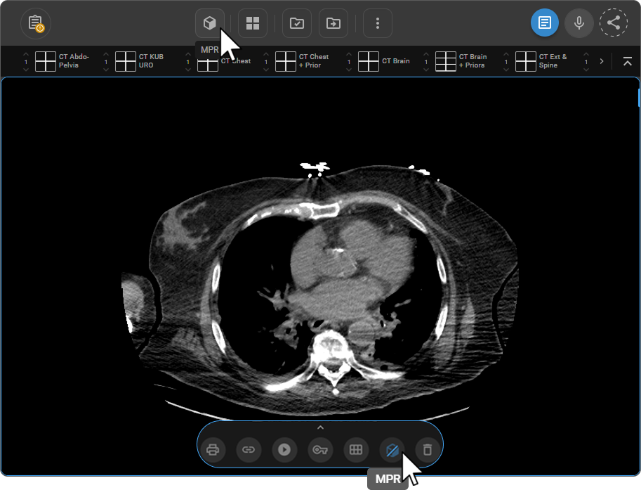
- From the Viewport Menu — click the MPR button at the bottom of the active viewport.
- From the toolbar — add via Customize Toolbar, then click MPR.
If the MPR button does not appear in the Viewport Menu, the selected series does not contain the geometry data required for reconstruction.
Interface
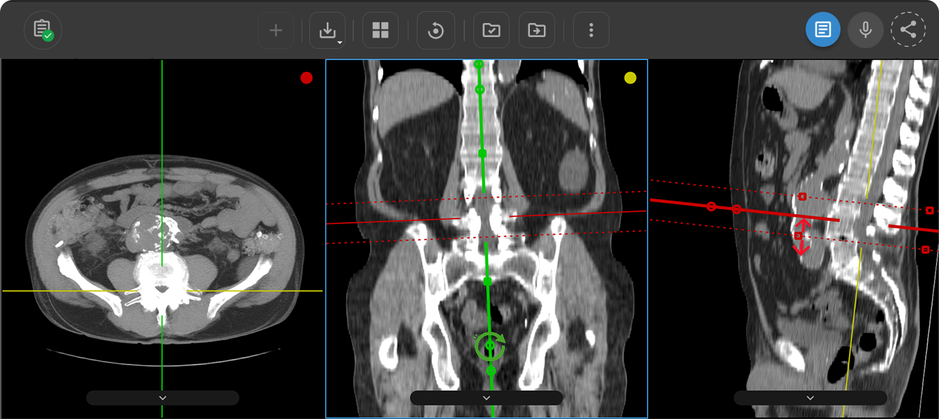
Upon activating MPR Mode, the viewer displays three viewports simultaneously — axial (left), coronal (center), and sagittal (right). Each viewport is identified by a colored dot in the top-right corner and color-coded crosshair reference lines that span all three planes:
| Plane | Dot Color | Crosshair Line Color |
|---|---|---|
| Axial | Red | Red |
| Coronal | Yellow | Yellow |
| Sagittal | Green | Green |
The crosshair lines are synchronized across all viewports — moving the crosshair in one plane updates the corresponding position in the other two planes simultaneously.

Highlighted Mode
Double-click any viewport to expand it for focused review. Double-click again to return to the standard three-plane layout.
Tools and Navigation
The following Adjustment tools are active in MPR Mode:
| Tool | Hotkey |
|---|---|
| Window / Level | W |
| Pan | T |
| Crosshair | J |
| Stack Scroll | S |
| Zoom | Z |
| Free Rotate | — |
Some tools may be disabled in this mode to ensure stability and performance.
Crosshair Interactivity
When you hover over any crosshair line, three interactive nodes appear along the line:
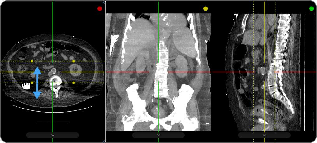
- Square node (center) — controls MIP Slab Thickness.
- First circular node (closer to center) — rotates both planes together.
- Second circular node (further from center) — rotates that plane independently.
Adjusting MIP Slab Thickness
Drag the square node at the center of the crosshair to control how much anatomical data is included in the projection. As you drag, two dashed boundary lines appear on either side of the crosshair line — moving them further apart increases the slab thickness and includes more data in the view; moving them closer reduces it.
Plane Orientation Controls
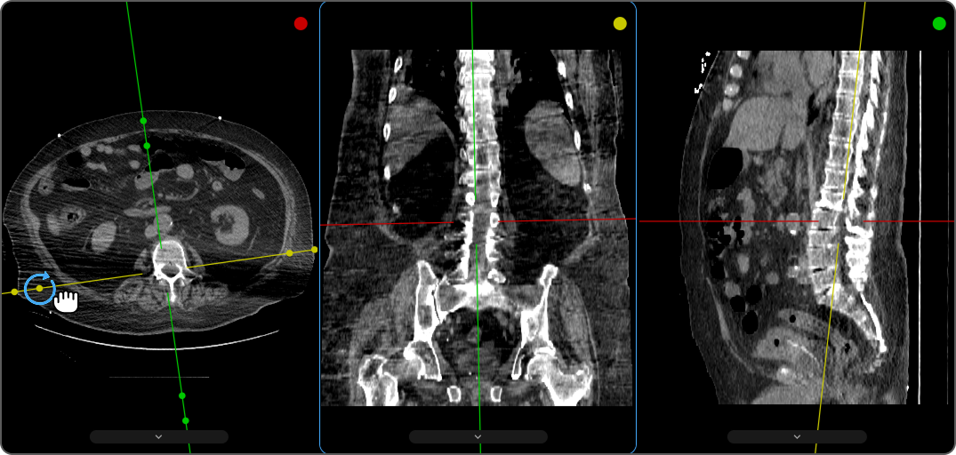
The two circular nodes along the crosshair line control how the reference plane is rotated:
- Drag the first circular node (closer to center) to rotate both planes together, maintaining their alignment for broader orientation adjustments.
- Drag the second circular node (further from center) to rotate that plane independently, without affecting the other planes.
Intensity Projection Modes
MPR Mode supports three intensity projection methods — MIP, AveIP, and MinIP — which define how voxel values are combined across the selected slab thickness.
To learn more, see MPR Intensity Projection Modes.